

Choosing an Aerofoil – what should we know?
Hammond’s first law of designing model gliders: Abandon hope…there is no free lunch and everything is a tradeoff.
Is there a best aerofoil?
I’m sure that I’m going to be controversial but anyway this is a myth. There is not and never can be a “best” aerofoil for any model application, as the way that the aerofoil is used and is positioned on the wing has such a huge effect. Good ones? — Yes, Great ones? — Probably. Best one? — Nope. There really is no one killer aerofoil that will blow all the others away, nor will there ever be one, and it doesn’t matter which application we are talking about.
Why not?
We demand a lot of different things from our aerofoils and some of those demands influence others, so at best we end up with a bit of a “Jack of all trades” — even if we are lucky enough or smart enough to come up with a good one. Some work better in outright speed, while some work better in the turns, just as some carry ballast better, and some stay up better — which is best? Speed, duration, DS, aerobatics, in fact anything; all will have at least 10 suitable aerofoils, leaving the designer to choose which one he thinks will be best for HIS application, or if not then he can design a section himself as I do.
Why do I design my own Aerofoils?
Because I can, and because most of my stuff is the result of some kind of study that I was paid to do, and more importantly, paid to test. I know more about them than any other sections, so of course I use them. I couldn’t tell you with my hand on my heart that they are better than others, but they are tried, and tested and so far, seem to work well in all the models I have designed around them.
Is the Aerofoil the Most Important Component of a Fast Model?
This is where I will get into real trouble, and I’ll probably have to suffer the second late heavy bombardment for this, but the answer here is no. It’s an important contributor for sure, but not the most important part of the whole. Having a good, fast, responsive, low drag aerofoil working for us is very important, but it’s not the key.
Planform: Wing planform, or how the (good) aerofoil is positioned and thus the lift is distributed over the entire wing is far more important and influential. Yet, surprisingly many people think that the aerofoil is the single biggest deciding factor in deciding what’s a killer plane versus an “also ran”. Logically it’s really no good having a super aerofoil if it’s distributed in the wrong positions across the wing, because however good it is, it just can’t do its job properly.
Simulation: Yes, some sections may be better than others when compared on a computer simulator, but the actual flying difference can be very slight and not enough to give any kind of clear advantage. There is in fact little practical difference in performance between most of the more often used modern and even some of the “ancient” aerofoils — and I have lost count of how many I have wind-tunnel tested over the years, so I can promise you that this is true.
Practical real time testing: Computer simulations may give some idea, and can help to compare one aerofoil against another to some degree, but believe me folks, it ain’t necessarily so. The results that you get on a computer simulator, and it doesn’t matter which one, can be quite different to what the aerofoil shows in wind tunnel or even more accurately, in flight testing. Just think about it, if computer simulations were perfect, or even in the ballpark, then why would organizations like NASA spend so many millions and millions of dollars constructing huge wind tunnels and test models? Has anyone ever seen the test unit at NASA Ames? You can get lost in there.
The flaws in computer simulation: First, computer testing is done in a digital, number-based bits and bytes environment and not in actual gaseous air. Yes, all the numbers can be manipulated to simulate different linear conditions, but the big problem is, we don’t fly in different linear conditions — we fly in chaotic constantly varying conditions that are impossible to accurately simulate. Heck, we don’t know what going to happen in the next ten seconds when we are flying.
Simulation Vs reality: In a computer simulation the digital air flows smoothly over the digital section and the results are displayed digitally according to the parameters we input. But, on the slope the non-linear air flows erratically over our physical section, and we make it worse by adding control inputs to the model. Imagine: on just one pass, in fact in just a few seconds, a MOM racing pilot is flying his plane while observing the three other models that are flying close to his behavior. What passes through the controlling pilot’s mind in ten seconds could be: “Looks like more lift on the right side…hold on…Is there more compression there? a bump…is that a thermal coming though?... S&*%t! too close to the edge! am I climbing slightly? Crap! now I’m diving slightly…Whoops…too close (MOM).”
All of these variables in most cases would result in small correcting control inputs…therefore the aerofoils spatial position changes constantly. This is reality.
Choosing an aerofoil type for the job you want it to do:
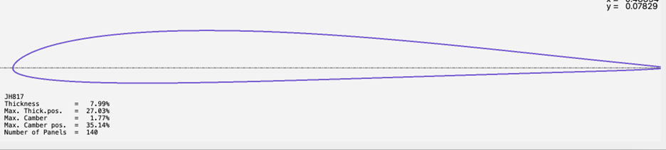
JH 817: This is the fastest and most responsive aerofoil section I have ever designed for a fast slope racer/allrounder. At this thickness range the section can deal with a large variation in model weight, yet its thin enough to be low drag, while still being thick enough to be pretty aerobatic, carry ballast, be structurally viable and be capable of withstanding high aerodynamic loads. There is no point going below a thickness of 7% because there will be little or no advantage on a slope soarer, and even possibly a loss of performance due to the wings having to be strengthened and made heavier to compensate for the lack of structure. By the same token there is no point in going over 8.5% as the extra lift is simply not needed, while the drag penalty escalates pretty fast with thicker sections.
JHSYM-10: This is a symmetrical section designed for a 2.5~3M span Big air Aerobatic model: For me, a modeler who always tries to get the very last drop of potential performance out of any airframe I design — whatever the discipline — there is only one choice for big air slope aerobatics and that is the fully symmetrical section — period.
I have heard cries of “symmetrical sections have no light wind soaring performance!” or protests like “I don’t want to compromise my light wind soaring performance with a symmetrical section!” for example. The point is that the object of the exercise when designing an aerobatic airframe is performance so I design for pilots who are way better than I will ever be.
If the flying speed of a good symmetrical section is maintained, then while a slope aerobat will never outsoar say an F3F plane — it will still have a more than reasonable performance, even in light air.
The best fully symmetrical aerofoil sections for slope aerobatics typically will be those that have a low drag when compared to their chord thickness. I had used the good old SD8020 for many years and many models, mostly because it had the lowest drag for its 10% thickness that I could find, until I was contracted to design some new ones that were not actually for model use.
A consideration which we now have the luxury of studying is the relationship between the control surface when deflected and the front of the section when flying. This is a big consideration for symmetrical F3F Horizontal Stabs for example where great fast handling is needed without the section letting go in a stall. Also, a big consideration for almost any slope soaring application is the alpha 𝜶 performance of the section (i.e. when the section is not actually flying parallel to the airflow across it, but at a positive or negative angle) If your chosen section will tolerate a nice bunch of sudden attitude changes without suddenly giving up on you, then you are clearly in a good situation.
Thickness plays a large part in our choice for aerobatic planes too — basically we need some, and for many years, in fact for the last series of five designs I opted for 10% as it seemed to be a good compromise between carrying energy and converting that energy to speed, however my latest design uses a 9% section — of my own devising as usual — I feel the need for a little more speed. For better drag performance and also improved control response and tolerance, I have found, and evidence shows that the double cusped sections offer possibly the best of both worlds.

This is the JHSYM-10 cusped symmetrical section. It’s the aerofoil that I use for stabilizers and aerobatic model main wings. This one was developed by me in response to a call for a low drag high response aerofoil. The designed aileron position is a generous 25% of the chord and the ‘high response’ part means that because of the cusps you get more response for less control movement. i.e. lower drag.
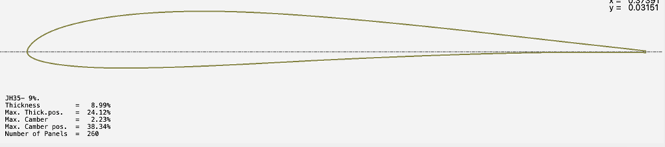
JH35. This is an aerofoil that I specifically designed to be used in Alpine soaring conditions. The Alpine soarer is probably a cross between a sloper and a flat field flyer like a Triangle GPS model. For alpine flying, let’s imagine a flying place that has suddenly been ‘de-restricted’ and by that, I mean that most, if not all of the slope restrictions have gone. No more need to fly in the compression band, no need to fly so close to the edge, no need to avoid rotors or no lift zones, and as long as the model can be seen then it’s mostly possible to fly further and wider than would be possible to fly on a simple slope.
For the new Alpenbrise model I’m using a new section: JH35–9 that has all the parameters I’m looking for to use for an alpine soarer. It’s an Undercambered section but really fast for all that and of course has a high lift profile.
JH25-8 This is a section that I adapted from a full sized – yes, those pesky drones again – high response type, as unusually when it got down to the lower scales in Reynolds numbers it still went pretty well. As you can see it is double cusped which can have the effect of allowing the boundary layer to stay put for a little longer, and even cause the airflow to give a slightly higher pressure at the trailing edge. – which of course can help control responses. With high control response, a pretty low drag profile, high lift coefficient and good alpha tolerance the JH25 yields a good bang for the buck. This one, like all of my sections was designed for a 25% chord aileron/flap hinge line. It’s used on my Corsa and Forza models so it’s well tried and tested.
